, Telecom Tigers: Networking
Showing posts with label Networking. Show all posts

Monday, February 24, 2020

IPv6 Features !!!

Hi All,
          Greeting from TelecomTigers Team,
Today, let discuss some features in IPv6, which makes it differ from IPv4,
Below are some basic information for IPv6,
  • Its a 128 Bit Address
  • Divided into 8 Segments
  • Each Segment is of 16 Bits
  • Each Segment is separated by ":" Sign
  • IPv6 Address Example - ACDF : 0A39 : 412F : B5E2 : 00FF : FF21 : 79EA : 0001
Features :-
  1. Longer Address Range - 2⌃128 Bits (3.4 x 10⌃38 Addresses)
  2. No Broadcast - It has (Unicast, Multicast, AnyCast)
  3. Single IP can be used by specific user at all places i.e. no need to assign new IP every time, as user changes his location,
  4. Single IP can be used for End to End Connectivity i.e. NAT feature not required
  5. IP Security (IPSec) - Optional but Available
  6. Quick Routing - All important information is at starting of Header which help in quick decision for routing
  7. Reduced Complexity in Header w.r.t IPv4,
                 IPv6 - Address Length (40 Byte with 8 Fields)
                 IPv4 - Address Length (20 Byte with 13 Fields)

Comments are most Welcomed,
ChEeEeEeRrRrSsS...
Telecom Tigers Team


For Clean & Green Future !!!
http://lightenmyways.blogspot.com


Tuesday, January 31, 2017

IPv6 (Internet Protocol Version 6)

Hi All,

   Greeting from TelecomTigers Team,

Today let discuss about IPv6 Protocol Overview,

           As we all know, that currently millions/billions of users are connected via Internet around the world, & there is continuous growth of Internet usage in Future too, which includes connection of various devices like mobiles/smartphone, vehicles, other devices, etc., which requires more n more unique IP's,

but there is certain amount of Unique IP's i.e. 2⌃32 Addresses (4,294,967,296 which is around 4 Billions Addresses) available with current IP Version i.e. IPv4 (Internet Protocol Version 4 which we normally call as - IP),

So, as the User Devices are Increasing day-by-day, we are running out of these unique IP's, & hence we need some other way & to overcome the issue, before all IP's are Utilized, our researchers came up with IPv6 i.e. Internet Protocol Version 6.

Note :- Its NOT a New Protocol but a New/Modified version of IPv4 (which was having limitation of Unique IP's).

In IPv6, we have Overcome the limitation of Unique IP's by Increasing it Bits Limit from 32 to 128 i.e IPv6 has 2⌃128  Addresses (3.4 x 10⌃38 Addresses), & also making it Hexa-Decimal which overall makes longer address location,

lets see some comparison between IPv6 over IPv4,

Advantage of Using IPv6 Over IPv4,
  • Provides More Addresses w.r.t IPv4.
  • Supporting Growth of Internet.
  • Provides Better Security.
  • Better Handling of IP's for All Devices. 

Comments are most Welcomed,

ChEeEeEeRrRrSsS...
Telecom Tigers Team
telecomtigers@gmail.com

Friday, April 19, 2013

Network Topologies


Hi All,
      Let's discuss today, about Network Topologies i.e. how devices within network are connected & how they can communicate with each other,
There are basically 2 ways to define network topologies:-
1     Physical TopologyThis defines Actual Layout of Wires or Media.
2     Logical Topology It define, how Media is accessed by Host for Transmitting    
      
      Below are the Different Topologies, by which Network can be Connected :
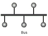
Bus Topology – This is the Simplest one i.e. In this, there is Single Backbone Cable which terminates at both end & all devices (computers, printers, laptops, etc.) are connected to this Cable. 
Advantage – 1) Easy to Connect any Device 2) Comparatively requires Less Cable Length. 
Disadvantage – 1) If Backbone cable Breaks, Entire Network Shut Down 2) Termination required at both end 3) Difficult to diagnose the Fault.

 ·        Ring Topology – In this each computer are connected to its previous & next computer, to form a path for data transmission like a Ring.
Advantage – 1) Organized 2) It doesn’t requires any Network Server for data transmission 3) Easy to identify the issue, when whole network goes down 4) chances of Collision are very Less.
Disadvantage – 1) Only 1 machine can transfer at a time 2) Each Data Packet must pass through each computer, whether they require or not, which makes it slow w.r.t. Star Topology 3) If 1 Machine fails, whole network is Down.
 Star Topology – As the name implies, it resembles STAR, in this each machine is connected to a central HUB & each machine has to pass through this HUB for data transmission among them. The HUB acts as Signal Booster or Repeater.
Advantage – 1) Easy to Install & Configure 2) Easy to Add or Remove Devices 3) Doesn’t impacts network, if any link goes down.
Disadvantage – 1) if HUB fails, whole network goes down 2) More expansive & more cable required than Bus Topology.
        Mesh Topology – This Provides maximum protection from Service Interruption, as in this, all machines are connected to each other which provides multiple routes to each machine.
Advantage – 1) Maximum Protection 2) Able to transmit data from one node to multiple node at a time 3) If 1 nodes fails, than there are alternate path for data transfer 4) Expansion or removal of nodes can be easily done, without disrupting other nodes. 5) Point-to-point link make fault identification and fault isolation easy.
Disadvantage – 1) Costly 2) Redundant paths, which may be of no use, from each node. 3) Network is Very Complex, hence maintenance is very tough. 
Tree Topology – It’s a Hybrid Topology i.e. Combination of Star & Bus Topologies, in which group of nodes are connected like in STAR topology & than many Stars-Connected Network are connected to each other via Main Bus.
Advantage – 1) Good Choice for Large Networks 2) Expansion & Management of Network is Easy 3) If one Segment is down, it doesn’t affect others.
Disadvantage – 1) If Central Bus goes down, whole network breaks. 2) Maintenance becomes difficult as the Network Grows. 

Keep checking for new posts till than HaPyYyYy Reading.

Comments are most Welcomed.
ChEeeeeeRs..
Telecom Tigers Team 
telecomtigers@gmail.com
http://homepageforu.webs.com/


Tuesday, March 12, 2013

Networking Devices

Hi All,

            Today let’s discuss something about different devices used in Networking Domain.
             These are used to connect different devices like computers, printers, scanners, etc. to a network, so that they can communicate easily.
             These devices are – NIC Card or LAN Card, Repeaters, Hubs, Bridges, Switches, Routers.
  • NIC Card (Network Interface Card) – It’s a PCB (Printed Circuit Board) Card in a Computer, & provides communication within locally connected devices. It has 48 bit serial number called MAC (Media Access Control) address. It’s a Layer-1 (Physical) & Layer-2 (Data Link Layer) device.
  • Repeaters – It’s a device used to Re-Generate the Signals. It regenerates electrical, wireless & optical signals. It helps to transmit signals to a longer distance, which becomes week due to transmission loss. 
  •  Hubs – These devices are used to connect different devices like computers, printers, etc. to a common LAN (Local Area Network), which helps to share resources. It’s like a Junction box, where LAN cables from different computers connects & allows computers to see network as a Single Unit. It’s a most commonly used device within house networks since it offers inexpensive option.     
  • Bridges / Switches – As the name implies, it provides communication between different LAN’s using same protocols like Ethernet. It’s a Layer-2 (Data Link Layer) device. In this, message is forwarded to every device using MAC address within network & only specific device (for whom message is addressed) responds. These devices are generally used within small networks since it broadcasts every message to each possible destination which would generate unnecessary traffic.
          Difference Between Bridge & Switches–
  1. Switch operates with Higher Speed than Bridge.
  2. Normally Switch has more ports than Bridge.
  3. Switch can operate in both (Half & full Duplex) mode, while Bridges only operates in Half-Duplex mode.
  4. Packet forwarding in Switches are hardware based, while in Bridge its Software based.
  • Routers – It’s a Layer – 3 (Network Layer) Device & filter data based on IP address. It helps in determining optimal path for transmitting data from network to another network.  It’s used to connect different LANs or a LAN with a WAN (e.g. the internet). It can regenerate signals, concentrate multiple connections, convert data transmission formats, and manage data transfers. It helps in controlling both Broadcast & Collision Domain.

Keep checking for new posts till than HaaaPPy Reading.

Comments are most Welcomed.
ChEeEeEeRs..
Telecom Tigers Team 
telecomtigers@gmail.com
http://homepageforu.webs.com/

Wednesday, December 19, 2012

OSI Reference Model

Hi All,

         Today let discuss something about OSI (Open System Interconnection) Model, which was created by  ISO (International Organization for Standardization), So that different manufacturer computers can communicate with each other by connecting them within network.

OSI Reference Model :-

            The OSI Model has 7 different layers, divided into 2 groups. The top 3 layers define how the applications within the end stations will communicate with each other & with users. The bottom 4 layers define how data is transmitted end to end,


1.    Application Layer: - It helps users to communicate with the computer. This layer comes into picture when it finds that user going to access the network soon. This layer acts as an interface between actual application program (which isn't at all part of layered structure, e.g. Internet Explorer (IE), Firefox, Google Chrome, Microsoft Office, etc.) & next layer down (i.e. Presentation layer) by providing ways for the application to send information down through the protocol stack. It’s also responsible for determining whether sufficient resources for the intended communication exist. Some programs which actually reside at this layer are FTP, TFTP, etc.
2.    Presentation Layer: - This layer is a translator i.e. it presents data to the application layer & is responsible for data translation & code formatting. It adapts the data into standard format which helps in successful data transmission, various tasks like data compression, decompression, encryption & decryption comes under this. 
3.    Session Layer: - This is responsible for Setting up, Managing, & then Tearing down the sessions between Presentation layer entities. It’s also provides dialog control between devices & nodes. It offers three different modes of communication: Simplex, Half Duplex, & Full Duplex. This layer basically keeps different application data separate from other application data.
4.    Transport Layer: - It provides end-to-end data transport service by establishing a logical connection between sending & receiving host on inter-network  This layer segments & reassembles data (from upper layers) into the same data stream. TCP (Transmission Control Protocol) & UDP (User Datagram Protocol) works at Transport Layer. This layer is responsible for providing mechanism for multiplexing upper layer applications, establishing sessions, & tearing down virtual circuits. It also hides details of any network dependent information from higher layers. This layer can be Connection-less or Connection-Oriented (Reliable Data Transfer).
5.    Network Layer: - It manages the network addressing. It tracks the location of the devices on the network & figure out the best way to route data packets. Device used in this layer are Routers & in Packet form data transmission occurs. 2 types of Packets are used – Data Packet & Route Update Packet.
Data Packet – It’s used to transport User Data & protocols used to support data traffic are called Routed Protocols, for e.g. IPv4, IPv6.
Route Update Packet – Used to update neighboring routers about the network connected. Protocols which send route update packets are called Routing Protocols, for e.g. RIP, RIPv2, EIGRP & OSPF. It helps to maintain routing tables on each router.
6.    Data Link Layer: - It’s a Hardware based Switching, It provides the physical transmission of the data & handles error notification (not correction), network topology, & flow control. It ensures that message delivered to the proper device on a LAN using Hardware address & translate message from network layers to Bits for Physical layer to transmit. It has 2 sub-layers,
      Media Access Control (MAC) 802.3 – It defines how packets are placed on the media. Error notification (not correction), ordered delivery of frames & optional flow control can also be used.
      Logical Link Control (LLC) 802.2 – In this, a host will receive the frame & looks in the LLC header, to find out the destination of the packet i.e. it is responsible for identifying Network layer protocols & then encapsulates them. It also provides flow control & sequencing of control bits. Switches & Bridges are used in this layer & uses Hardware (MAC) address to filter the network. 
7.    Physical Layer: - It specifies the electrical, mechanical, procedural, & functional requirement for Activating, Maintaining, & Deactivating a physical link between end systems. Hubs & Ethernet are used in this layer.

Below is the Summary of all OSI Layers Functioning,

Keep checking for new posts till than HaPPy Reading.

Comments are most Welcomed.

ChEeEeEeEeEeRrRs
Telecom Tigers Team 
telecomtigers@gmail.com
http://homepageforu.webs.com/

Friday, November 23, 2012

What is IP (Internet Protocol)

Hi All, 
    Greetings,
In today’s scenario major part of telecom is shifted towards Data (IP Backbone) which helps, to reduce the cost, enhance the performance/efficiency of the network, hence we are shifting TDM based system towards IP Based,
So let’s just know something about IP addresses.

What’s IP (Internet Protocol) Address:-
          It’s a numerical label assigned to each device (e.g., computer, printer) participating in a computer network that uses the Internet Protocol for communication. 
          It’s a 32-bit number, It is represented in dot-decimal notation, which consists of 4 decimal numbers, each ranging from 0 to 255, separated by dots, e.g., 127.0.0.1 (Loop Back Address). 
Each part represents a group of 8 bits (octet) of the address.

         It serves 2 Principal Functions :-
  1. Identifies the system's network address &
  2. Identifies which particular machine it is on the network, The Host part.
IP addresses are divided into 5 classes -

Class A addresses are assigned to larger networks,
Class B addresses are used for medium-sized network,
Class C for small networks,
Class D for Multicasting,
Class E for Research Organizations – Experimental Purposes.

Details :-
Note :- Till now we are using IP address as IPv4 (32 Bits) but due to enormous growth of Internet & decreasing amount of available addresses, a new version of IP address is developed i.e. IPv6, which is 128 Bits & its implementation is ongoing.
             The preferred IPv6 address representation is: xxxx:xxxx:xxxx:xxxx:xxxx:xxxx:xxxx:xxxx where each x is a hexadecimal digit (0-9, A-F) representing 4 bits, This notation is commonly called string notation.


More information, updated soooonnnnn...


Keep checking for new posts till then HaPPy Reading.

Comments are most Welcomed.

ChEEEEEERrRs
Telecom Tigers Team 
telecomtigers@gmail.com
http://homepageforu.webs.com/
 
Template design by Amanda @ Blogger Buster